Installing and adjusting the mold on the hydraulic press is a very important task, which will directly affect the quality and production safety of the parts. Therefore, when installing and adjusting stamping molds, you must not only be familiar with the structural performance of the press and mold, but also understand the process characteristics of the mold, the machining accuracy requirements, and the nature of the stamping process. Different presses are selected according to the external dimensions of the mold.
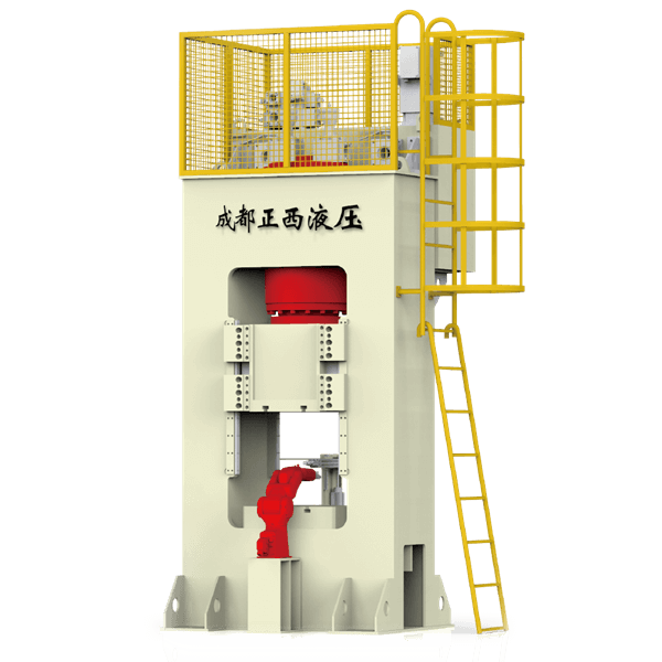
Commonly used stamping equipment includes open die presses, closed die presses, double-action presses, multi-station presses, cold extrusion presses, fine blanking presses, and high-speed presses.

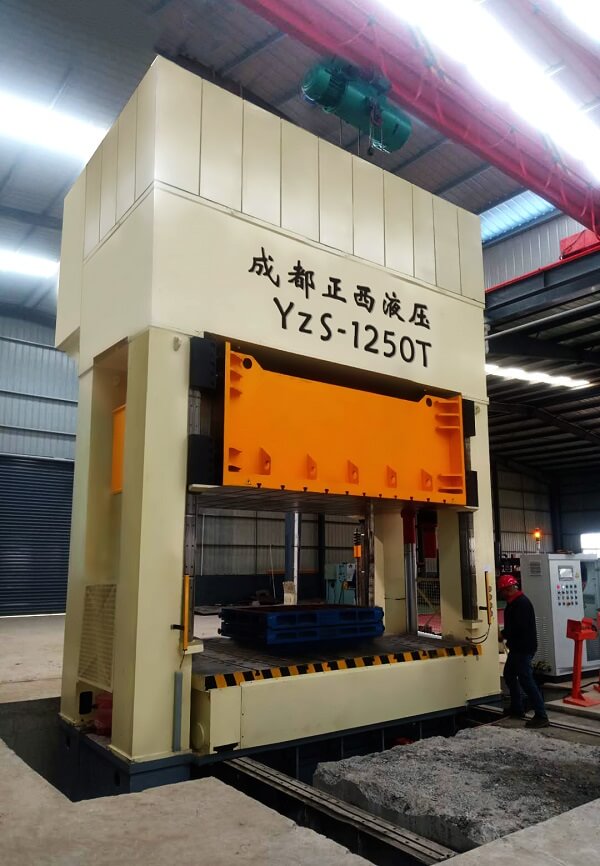
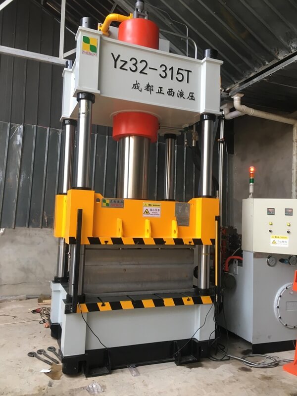
Install the Mold on the Hydraulic Press
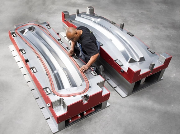
- Placement of stamping mold
Place the closed stamping mold on the workbench pad of the press, and clean the upper surface of the upper mold and the lower-end surface of the punch slide. Use your hand or a pry bar to turn the press’s flywheel (large presses should have the motor turned on). At the same time, adjust the position of the mold on the workbench pad so that the template is in the die handle hole of the press slider. Fasten the mold handle with the pressing block and the tightening bolts on it. At the same time, keep the upper surface of the upper mold base in contact with the bottom surface of the press slide. - Press the lower mold tightly
Correct the position of the lower mold according to the upper mold, and then use the pressure plate and bolts to press and position the lower mold. - Adjust the mold height
Remove the wooden spacer between the upper and lower molds. Turn the flywheel by hand or a pry bar to move the slider to the bottom dead center. Loosen the locking nut of the press adjusting screw, turn the adjusting screw to keep the male and female molds in the predetermined position, and then lock the screw.
- Adjust the position of the stop screw on the press slider
For molds that require a rigid push, the position of the stop screw must be appropriate. The pushing action occurs when the press is at the top-dead-center position. For molds that do not require a rigid push, the position of the stop screw should not hinder the normal operation of the mold. After adjusting the press according to the above steps, the power can be turned on and test punching can be carried out.
Key Points for Mold Adjustment
- Adjustment of the relative position of the convex and concave mold edges
For unguided dies, when the upper and lower dies are installed on the press, their working parts (punch and concave die) are engaged. The depth of the punch entering the die should be moderate, not too deep or too shallow, as long as the finished product can be punched out. The adjustment is achieved by adjusting the length of the press connecting rod. - Gap adjustment of convex and concave molds
For guided dies, as long as the guide parts can move flexibly without any astringency, the gap can be ensured to be uniform. For non-guided punches, to make the gap uniform, the edges of the die can be lined with copper or cardboard for adjustment. You can also use feeler gauges and light transmission testing methods to adjust the press until the convex and concave molds of the upper and lower molds are aligned with each other and the gaps are even and then tighten the template with screws to the working surface of the press before proceeding. Test run.
- Adjustment of the positioning device
When adjusting the die, the stability and reliability of the positioning of the blank should be fully ensured. Always check whether the positioning pins, positioning blocks, and positioning rods meet the positioning requirements. If the position is inappropriate and the positioning shape is inaccurate, the position and shape should be adjusted in time, and the positioning parts should be replaced if necessary. - Adjustment of the unloading system
The unloading plate (ejector) of the unloading system should be adjusted to fit the punched parts. The discharge spring or discharge rubber elasticity must be large enough. The stroke of the unloading plate should be adjusted to a position sufficient to discharge the products. The leakage hole should be unobstructed. The punching rod and pushing rod should be adjusted to push out the product smoothly without getting stuck or astringent. - Guidance system adjustment
The guide pillars and guide sleeves of the mold must have good matching accuracy, and no position deviation or stiffness may occur.

Disassembling the Mold on the Press
- Use your hand or a crowbar to turn the flywheel of the press to lower the slider of the press. Place wooden spacers between the upper and lower molds to close the mold.
- Loosen the tightening screw on the press slider that is used to press the mold handle’s pressure plate, and gently tap the upper mold to truly detach the slider from the mold handle. Then raise the slider to the top dead center position and separate it from the upper mold.
- Finally, loosen the bolts and pressure plate holding the lower mold, and move the mold out of the workbench. During the entire disassembly process, full attention should be paid to safe operation and the rotation of the motor should be stopped as much as possible to avoid accidents.
Issues that Should Be Paid Attention to When Installing Stamping Molds
- Personal safety should always come first.
- For punch dies with infinite positioning devices, a backing board should be added between the upper and lower dies.
- After the punch table is cleaned, place the clamped mold to be tested in a suitable position on the table.
- Select the press slider stroke according to the process documents and die design requirements, adjust the slider connecting rod, move the mold, and ensure that the mold handle is aligned with the mold handle hole and reaches the appropriate mold mounting height. Generally, the punching die first fixes the lower die (without tightening it) and then fixes the upper die (tightens it). The T-bolts of the pressure plate should be tightened with a suitable torque wrench (lower die) to ensure that the same bolts have consistent and ideal pre-clamping force.
Issues that Should Be Paid Attention to When Debugging Stamping Molds
- Before the mold trial, fully lubricate the mold and prepare materials for normal production. Start the punching die during the idle stroke and confirm the mold is operating normally 3 to 5 times before trying punching again.
- Adjust and control the depth of the punch into the die, and check and verify the performance and operational flexibility of mechanisms and devices such as die guide, feeding, pushing, lateral pressure, and elastic pressure. Then make appropriate adjustments to achieve the best technical state.
- Test punch 3, 5, and 10 pieces of large, medium, and small dies respectively for initial inspection after production is stopped. After passing the test, 10, 15, 30 pieces will be tested again for re-inspection.
- After scribing inspection, punching surface, and burr inspection, all dimensions and shape accuracy must meet the drawing requirements before delivery for production.