A hydraulic press is a pressure-processing machine that can be used to process various materials such as metal, plastic, wood, leather, rubber, etc. It can complete forging, stamping, folding, cold extrusion, straightening, bending, forming, packaging, and other processes. At the same time, it also has the advantages of step-less adjustment of pressure and speed in a wide range, full power output at any position, and required pressure, so it is very versatile.
This article will mainly analyze the design of the hydraulic press, including the design of the main structure, the design of the hydraulic control system, and the design of the electrical system.
Main Structure Design
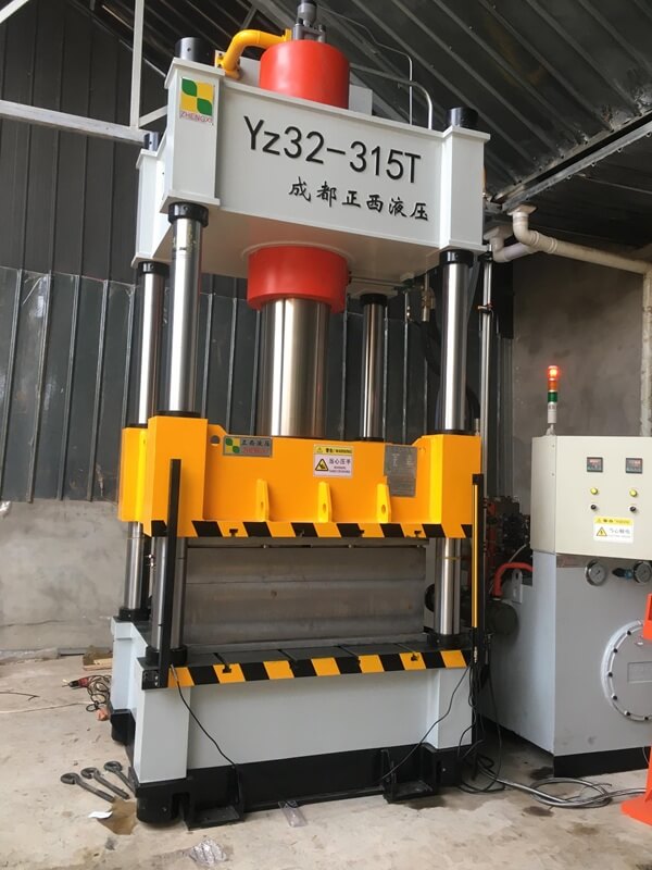
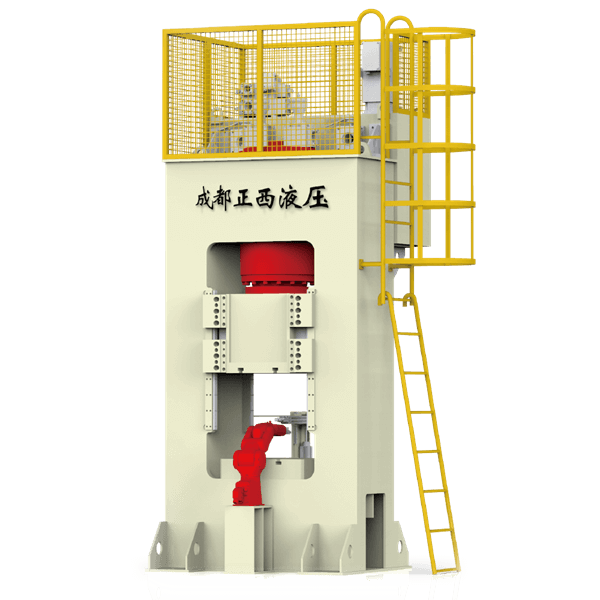
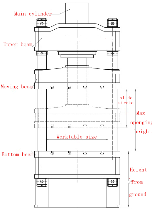
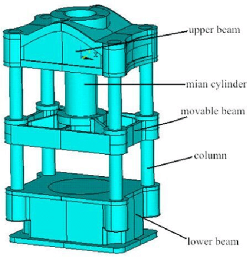
The four-column hydraulic press is the most common and widely used structural form among hydraulic presses. It adopts the traditional “three beams and four pillars” main engine model. This type of main engine is mainly composed of a main cylinder, a beam, a slider, a guide column, and a workbench. The structure diagram is shown in the figure.
The fuselage of the four-column hydraulic press is composed of an upper beam, a working cylinder (lower beam), and four columns. The working cylinder is installed in the upper beam. The movable beam is connected with the working cylinder as a whole, moves up and down guided by the column, and transmits the force generated in the working cylinder to perform pressure processing on the workpiece. Since the fuselage is connected into an integral frame, the fuselage bears the entire working force.
1. Column Design
Material selection: The column is an important support and force-bearing part of the four-column hydraulic press, and it is also the guiding reference of the movable beam. Therefore, the column should have sufficient strength and rigidity, and the guide surface should have sufficient precision, smoothness, and necessary hardness. The material of the guide post is 45-round steel, and forgings can also be selected.
Heat treatment requirements: In addition to bearing the tensile force of the column, there is also friction between the outer cylindrical surface and the slider. In order to reduce the wear on the surface of the guide post, the surface hardness is improved by surface heat treatment to increase the surface friction resistance. The overall heat treatment process is quenching and tempering and surface quenching.
Its structural form is as follows: the upper beam is supported by the column platform adjusting nut, the column shoulder is supported on the work surface, and the two ends are locked with locking nuts.
2. Post Nut Design
Since the column is connected with the upper and lower beams by column nuts to form a rigid frame, it is the basic condition to maintain the rigidity of the frame to ensure that the column nuts are tightened so that they are closely matched with the bonding surfaces of the upper and lower beams without loosening. The column nut is generally round and can be made into integral type and split type. The material can generally be 45 forged steel.
During installation, the column needs to be locked with nuts. Its preloading principle and basic method are similar to the preloading of the combined fuselage of the universal crank press. After the nut is pre-tightened, it must be locked with an anti-loosening device to prevent the nut from falling off.
3. Beam Design
The beam includes the upper beam, the lower beam (or workbench), and the movable beam, which is an important part of the hydraulic press. There are two main structural forms for small and medium-sized hydraulic presses: casting and welding. However, no matter whether the upper beam is composed of casting or welding, necessary heat treatment should be carried out to eliminate its internal stress.
Shape and size requirements: The upper beam is located on the upper half of the column, used to install the working cylinder and bear the reaction force of the working cylinder. In order to make the composed space meet the requirements and the piston run smoothly, it is required that the axis of the upper beam installation cylinder hole and the shoulder plane of the installation cylinder should be perpendicular. The contact surface of the upper beam and the adjusting nut should be parallel to the contact surface of the oil cylinder shoulder, and the upper and lower planes of the column passing through the hole should be parallel, and so on.
Its specific requirements are:
(1) The non-perpendicularity tolerance between the axis of the main cylinder hole and the cylinder shoulder fitting plane is less than 0.2mm.
(2) The tolerance of non-parallelism between the contact plane of the adjusting nut and the joint plane of the cylinder shoulder is less than 0.2mm.
(3) The unevenness tolerance between the contact surface of the lock nut and the contact surface of the adjustment nut (the upper surface and the lower surface of the column passing through the hole) is <0.16mm.
(4) The non-parallelism tolerance between the cylinder lock nut plane and the cylinder shoulder fitting plane is <0.12mm.
(5) The matching tolerance with the outer circle of the oil cylinder is H8/f9 or higher than this level.
(6) The size of the column hole is 1mm larger than the diameter of the column insertion end.
4. Slider Design
The main function of the slider: it is connected to the piston rod of the main cylinder to transmit the pressure of the press. It reciprocates up and down along the guide surface of the guide post through the guide sleeve. Need better strength, stiffness, and guiding structure. The slider material is also ZG35.
Structural form: According to the nature of the pressing process, the slider cannot be bent anyway, so the slider is usually a box beam with an open top, and the height can be designed to be lower.
Shape and size requirements: The slider is the main moving part of the hydraulic press. In order to ensure the precision requirements of the hydraulic press, it is required that the axes of the guide bushings of the four guide posts should be parallel to each other. It should be parallel to the centerline connecting the bore of the piston rod. These hole axes all should be perpendicular to the lower plane of the movable crossbeam.
The connection with the piston rod can be divided into movable connection and fixed connection.
5. Workbench Design
Structural form: The workbench is the installation base of the host. Fix the mold on the table. Bear the weight and full load of the machine body during work. An ejection cylinder, return cylinder, and other auxiliary devices can also be installed. The structural form of the workbench is the same as that of the upper beam.
Requirements for shape and size: The workbench is the basic part of the whole machine, and it is the standard for installing abrasive tools, as well as the ejector cylinder and other components. Therefore, there should be necessary technical requirements for the unevenness of the work surface and the installation and positioning base surface of each component.
Connection with the ejector cylinder: use screws and flanges to fix the ejector cylinder on the workbench.
The structure of the fixed mold: In order to fix the mold, there is generally a T-shaped groove on the work table, which is processed according to the standard size of GB158-59.
Processing technical requirements:
- Castings must not have defects such as pores, shrinkage cavities, slag inclusions, cracks, etc. of image quality.
- Castings must be cleaned of molding sand, burrs, and risers should be removed and polished, and the non-processed surfaces of beams should be painted with red anti-rust paint.
- Castings should be annealed before processing to eliminate internal stress.
- Casting materials should be tested for mechanical properties and can only be implemented after meeting the requirements of HT20-40.
- For the unevenness of the workbench, the tolerance is 0.1mm according to the JB1293-73 standard.
Hydraulic Control System
The composition of the hydraulic press system.
Hydraulic energy device: provide liquid pressure, common energy devices include hydraulic pumps and pressure tanks, etc.
Hydraulic actuators: perform work tasks, including hydraulic cylinders, hydraulic motors, hydraulic valves, etc.
Hydraulic transmission pipeline: transmit the liquid to the actuator, including pressure pipes, oil pipes, connectors, etc.
Hydraulic control components: used to control the flow and pressure of liquids, including pressure control valves, flow control valves, directional control valves, etc.
Electrical control components: used to control the start, stop, steering, and speed of the hydraulic system, including switches, electrical controllers, solenoid valves, and monkeys.
The components of the hydraulic control system can be combined and adjusted according to specific applications and requirements to meet various engineering needs.
The hydraulic control system should generally meet the following basic requirements:
1) It can correctly realize various strokes and actions of the main working cylinder and its auxiliary mechanism hydraulic cylinder, and meet the speed requirements of these strokes and actions.
Generally speaking, the speed of approaching and returning the empty journey is required to be fast in order to save time and improve productivity. The speed of the working stroke is determined according to the process requirements, and is generally relatively slow, so as to avoid excessive requirements on the total power of the unit. However, the speed requirements of various processes for the working stroke are very different. On some hydraulic machines, there are also micro-movement requirements when setting the mold.
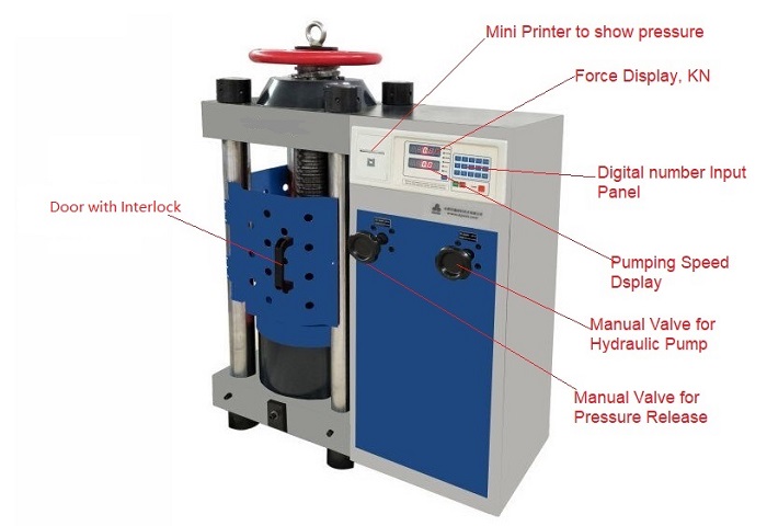
2) The operation should be light, flexible, safe, and reliable. The actions of the main working cylinder and the auxiliary mechanism must be coordinated, and there should be an interlock device if necessary.
3) The components of the control system should have a long working life and not be easily damaged. Some wearing parts must be replaced or easily maintained.
4) No leakage or very little leakage to keep the working environment tidy.
5) Parts and hydraulic components should meet the corresponding national standards (GB) or departmental standards (JB).
Electrical Control System
1. Controller Design
A programmable logic controller (PLC) has a great cost advantage over industrial control computers and has outstanding control advantages over relays. It has the advantages of fast time response, high control precision, good reliability, a control program that can be changed with the process, easy to connect with the computer, easy to maintain, small in size, small in quality, and low in power consumption. At present, it is widely used in medium and small hydraulic presses for various general purposes.
The basic hardware composition of PLC
1) Central processing unit (CPU);
2) memory (system memory and user memory);
3) Input and output interfaces;
4) power supply
The software composition of PLC includes system software and the user program. The programming languages for its applications are most commonly Ladder Diagram (LAD) and Instruction List (STL).
2. Electrical Control Cabinet Design
The electrical control system corresponds to a dedicated control cabinet, which is used to place electrical components such as PLCs and contactors and to realize power supply configuration. It is the link of energy transmission between the power supply, power transmission equipment, and presses.
Structural features: The cabinet body of the GGD AC low-voltage power distribution cabinet adopts the form of a general cabinet. The frame is partially welded and assembled with 8MF cold-formed steel, and has 20 die-mounting holes, with a high universal coefficient. GGD fully considers heat dissipation. There are different numbers of cooling slots at the upper and lower ends of the cabinet. When the electrical components in the cabinet heat up, the heat rises and is discharged through the upper slot. The cold air is continuously supplemented into the cabinet through the slots at the lower end so that the sealed cabinet body forms a natural ventilation channel from bottom to top to achieve the purpose of heat dissipation.
According to the requirements of modern industrial product modeling design, the GGD cabinet adopts the method of the golden ratio to design the shape of the cabinet body and the division size of each part, so that the whole cabinet is beautiful and generous, and has a new look. The top cover of the cabinet can be removed when necessary, which is convenient for the assembly and adjustment of the main busbar on site. The four corners of the cabinet top are equipped with lifting rings for lifting and shipment.
That’s all there is to know about hydraulic press design. Zhengxi is a Chinese manufacturer of high-quality hydraulic presses, with rich technical personnel and strong production strength. Follow us to learn more about hydraulic presses.